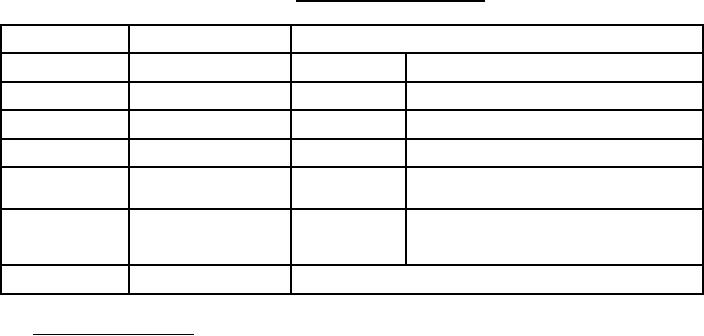
F-F-320C
TABLE I. Performance requirements.
Factory-assembled
Field-assembled
Group
(group 1)
(group 2)
Type
I
II
III
I
II
III
Style
-
-
C
-
-
A
B
C
D
Class
-
-
-
-
-
-
-
-
1
2
Minimum rated face
400
400
400
400
400
400
400
400
400
400
velocity, ft/min (m/s)
(2 032)
(2 032)
(2 032)
(2 032)
(2 032)
(2 032)
(2 032)
(2 032)
(2 032)
(2 032)
Minimum efficiency at
90
90
90
90
90
90
90
90
90
90
rated capacity and face
velocity
Maximum initial
0.25
0.25
0.50
0.25
0.25
0.25
0.50
0.50
0.50
0.60
resistance with after-
(6.35)
(6.35)
(12.70)
(6.35)
(6.35)
(6.35)
(12.70)
(12.70)
(12.70)
(15.24)
filters in place, inches
(mm) water gage
Range of capacities,
1,000 to 40,000 cfm
1,000 to 175,000 cfm
cfm (m3/s)
(0.47 to 18.88 m3/s)
(0.47 to 82.59 m3/s)
3.8 Details of components.
3.8.1 Enclosure panels. Group 1 units shall be housed in a factory-assembled cabinet which
includes top and side panels, a base mounting, and for units with washwater systems, a drain pan.
Side access doors or detachable panels shall be provided to permit removal of the collector cells.
Sheet metal panels and the drain pan shall have a thickness of not less than 18 gauge (1.27 mm).
Group 2 units shall be furnished with side panels and a top plate for assembly at the site. The
group 2 panels shall have a thickness of not less than 16 gauge (1.59 mm). Enclosure panels for
both group 1 and group 2 units shall be galvanized sheet steel unless alternate materials or
protective coatings are authorized under the contract (see 6.2). Cabinets for group 1 units shall
be equipped with slide rails to facilitate end removal of the cells.
3.8.2 Ionizing-collecting cells. The ionizing-collecting cells shall be of the two-stage electrostatic
type. The cell shall consist of an ionizing section and a section composed of alternately grounded
and charged plates on which the particulate matter is collected. The cells shall be designed to
permit disconnection or removal of one cell without affecting the remaining cells in the bank. The
physical separation between the collector plates shall be sufficient to withstand the design
potential of the power supply under all normal operating conditions. Where a potential difference
exists between the ionizing grid and the collector plates, a physical separation sufficient to
withstand this differential under rated operating conditions shall be incorporated in the design.
3.8.3 Power packs. Each filter unit shall be supplied with a power pack(s) of proper quantity and
size to convert the specified primary power to the required secondary voltages and current
outputs for the ionizing and plate sections. Typical voltages for the ionizing and plate sections are
12,000 and 6,000 volts direct current, respectively. Each power pack shall be equipped with:
a. A power pilot-light.
b. A current-indicating device in the secondary circuit.
c. Overload protection that provides automatic shutoff in the event of a dead short circuit,
but permits continuous operation under temporary overload or momentary short circuit.
6
For Parts Inquires submit RFQ to Parts Hangar, Inc.
© Copyright 2015 Integrated Publishing, Inc.
A Service Disabled Veteran Owned Small Business